
Analog and Digital Electronics Laboratory
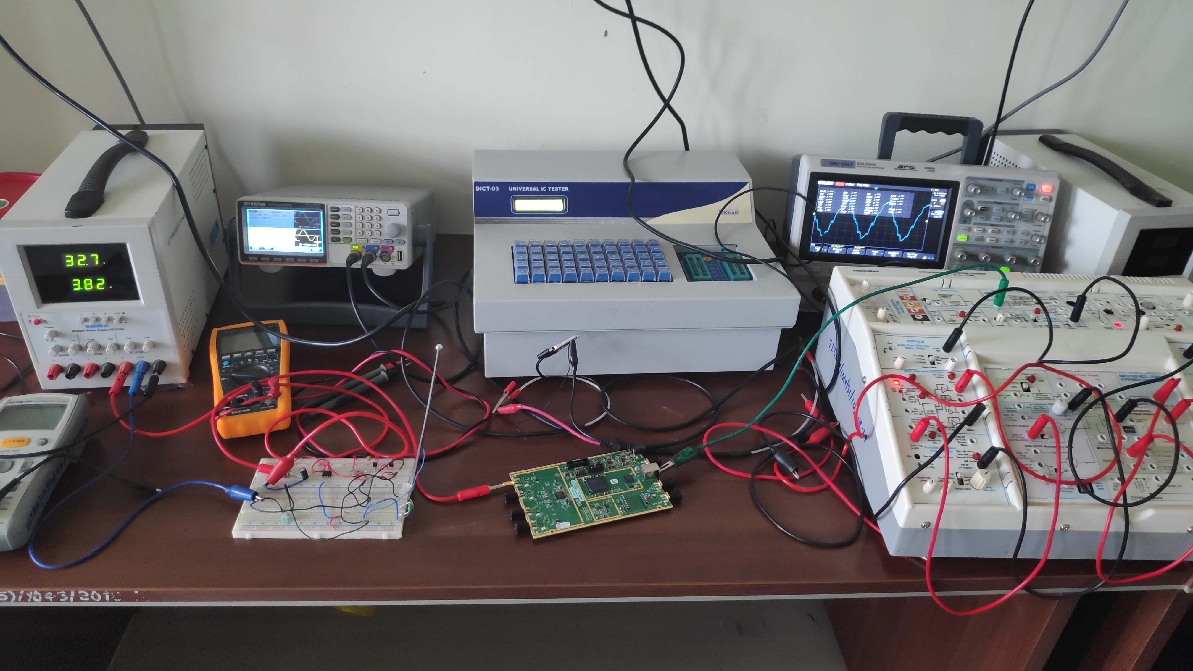
The Analog & Digital Electronics Laboratory is accessible to undergraduate students of all the departments. The lab is well equipped with Digital Storage Oscilloscopes, function generators, digital multimeters, Analog & Digital ICs, general purpose ICs, etc.
Lab Equipment’s: -
-
Two channel 100 Mhz Digital Storage Oscilloscope (Model: SMO1002; Make: Scientific)
-
25 MHz single Channel Function Generator (Model: SMG5225; Make: Scientific)
-
Triple output Regulated DC Power Supply (Model: PSD3304 Make: Scientific)
-
4½ Hand Held Digital Multimeter (Model: SM7024, Make: Scientific)
-
Universal IC Tester (Model: DICT-03, Make: Kitek)
-
LCR Meter (Model: LCR-914, Make: GW-Instek)
-
Analog Kit (Model: ASLK PRO, Make: Texas Instruments)
Lab Experiments of all the UG course: -
-
Electrical Science Lab: -
-
Familiarization with the laboratory equipment and basic components.
-
Measure the I-V Characteristics of a Forward Bias and Reverse Bias Diode.
-
Design and analysis of clipping and clamping circuits.
-
Volt-Ampere Characteristics of Zener Diode and Zener Voltage regulator characteristics.
-
Design and Study 555 Timer applications.
-
To design the resonant frequency, quality factor and band width of a series resonant circuit.
-
Designing of Low Pass Filter & High Pass Filter.
-
Analog Circuits Laboratory: -
-
Determine the frequency response of RC coupled Amplifier.
-
Realize BJT Darlington Emitter follower with and without bootstrapping.
-
Demonstrate the operation of non-inverting and inverting circuits using Op-amp.
-
Characteristic of MOSFET.
-
RC Phase Shift Oscillator.
-
Digital Design Laboratory: -
-
To simplify the given expression using K-map and to realize it using Basic gates and
Universal gates.
-
To realize (a) Half Adder, and Full Adder and (b) Half Subtractor and Full Subtractor
by using Basic gates and NAND gates only.
-
To design and set up the following circuit using IC 7483 (a) A 4-bit binary parallel
adder, and (b) A 4-bit binary parallel subtractor.
-
To design and set up the following circuit (a) 4:1 Multiplexer (MUX) using only
NAND gates, and (b) 1:4 DE multiplexer(DE-MUX) using only NAND gates.
-
To design and set up the following circuit (a) verify the various functions of IC
74153(MUX) and IC 74139(DEMUX), and (b) set up a Half/Full Adder and Half/Full
Subtractor using IC 74153.
-
To realize and study Ring Counter and Johnson counter.
-
Semiconductor Devices & Circuits Laboratory: -
-
Familiarization with the laboratory equipment and basic components.
-
Measure the I-V Characteristics of a Forward Bias and Reverse Bias Diode.
-
Design and analysis of clipping and clamping circuits.
-
Volt-Ampere Characteristics of Zener Diode and Zener Voltage regulator characteristics.
-
Design and Study 555 Timer applications.
Faculty In-charge: - Dr. Sanjay Kumar
Email id:- skumar.ece@iiitbh.ac.in
JTS: - Mr. Kumar Sheelvardhan and Mr. Rajan Kumar
VLSI & DSP Laboratory